


Overview

Figure 1: Thomas Tetrode tip. The Thomas tetrode consists of a unique fiber (OD=100µm) with 4 individual metal cores inside and a quartz glass insulation surrounding the metal wires. The metal is an alloy of 95% platinum and just 5% tungsten. The tetrode tip is highly reproducible by using unique manufacturing techniques. The smooth tip shapes reduces tissue damage to a minimum, in comparison to twisted wire or silicon tetrodes.
Thomas tetrodes are the only tetrodes presently available that can be adapted to different cell densities in different species or brain areas.
Tip shape A (pulled & ground tip, impedance 1-2MΩ) is well suited for brain areas with higher cell densities (e.g. rat cerebellum).
Tip shape D (just ground, impedance 500-800kΩ) is well suited for brain areas with “normal” cell density (e.g. monkey cortex).
The Thomas tetrodes are available for Thomas Microdrive systems (see figure 3) and can be easily customized to be used with other than Thomas microelectrode manipulator systems (see figure 4).
The recording radius and spatial selectivity of an extracellular probe are important for interpreting neurophysiological recordings but are rarely measured. Moreover, an analysis of the recording biophysics of multisite probes (e.g., tetrodes) can provide for source characterization and localization of spiking single units, but this capability has remained largely unexploited. The research group of Prof. Dr. Jonathan Victor at Cornell University in New York has addressed both issues by using Thomas tetrodes quantitatively and published the results (for details see
The Thomas tetrode working principle was evaluated in the Bernstein Center for Computational Neuroscience (BCCN) research project “Memory Network“ (see poster presentation: Memory Networks – Thomas Tetrode Evaluation; Klaus Obermayer, Matthias Munk, Uwe Thomas, Dirk Hoehl, Poster Presentation, Bernstein Center Evaluation Meeting, Berlin, 2007)
The tetrodes are available with two different tip shapes (see figure 2)
 Figure 2: Tip shapes of Thomas tetrodes. Tip shape A is a double conical tip shape well suited for single unit isolation in brain areas with higher cell densities (e.g. rat cerebellum).
Thomas tetrodes are the only tetrodes presently available that can be adapted to different cell densities in different species or brain areas.
Tip shape A (pulled & ground tip, impedance 1-2MΩ) is well suited for brain areas with higher cell densities (e.g. rat cerebellum).
Tip shape D (just ground, impedance 500-800kΩ) is well suited for brain areas with “normal” cell density (e.g. monkey cortex).
The Thomas tetrodes are available for Thomas Microdrive systems (see figure 3) and can be easily customized to be used with other than Thomas microelectrode manipulator systems (see figure 4).
 Figure 3: Thomas tetrode for Thomas Microdrive system with rubber tube unit and pulling string. As already mentioned the tetrode is available with two different tip shapes according to the adaptation to different species and different brain areas with different cell densities (see tetrode data sheet for details).
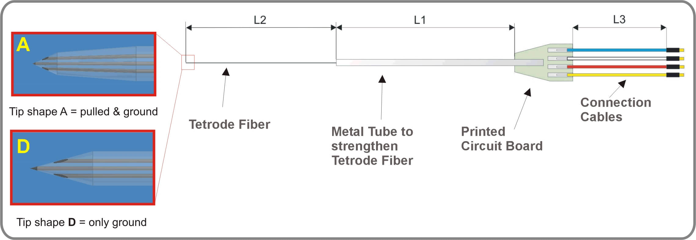 Figure 4: Thomas tetrode for other electrode microdrive systems. In this case the fiber is strengthened with a metal or glass tube instead of the Thomas rubber tube drive unit. The metal or glass tube strengthens the thin tetrode fiber. As already mentioned the tetrode is available with two different tip shapes according to the adaptation to different species and different brain areas with different cell (see tetrode data sheet for details).
After Reitboeck [5] and Eckhorn [6], the Thomas microelectrode and tetrode manufacturing technique has some advantages in comparison to other tetrode or microelectrode techniques presently used for neurophysiology. These advantages are the following (for details see [5]):
1. The shaft of the fiber electrodes, over the whole penetration depth, is cylindrical and very thin (see REM photo below). Tetrodes with 90 – 100µm and microelectrodes with outer diameters of 20 – 80 µm and also down to the nanometer scale have been made in the last 20 years. Due to their small dimensions these fiber electrodes only cause minimal tissue damage. (see for example [7], [8]). Horton and Adams reported [9]:”…Because tetrodes leave no visible tissue tracks and cortex becomes distorted in the flatmounting process, only data from recording sites in the immediate vicinity of a lesion could be reliably assigned to layer 4C…“.
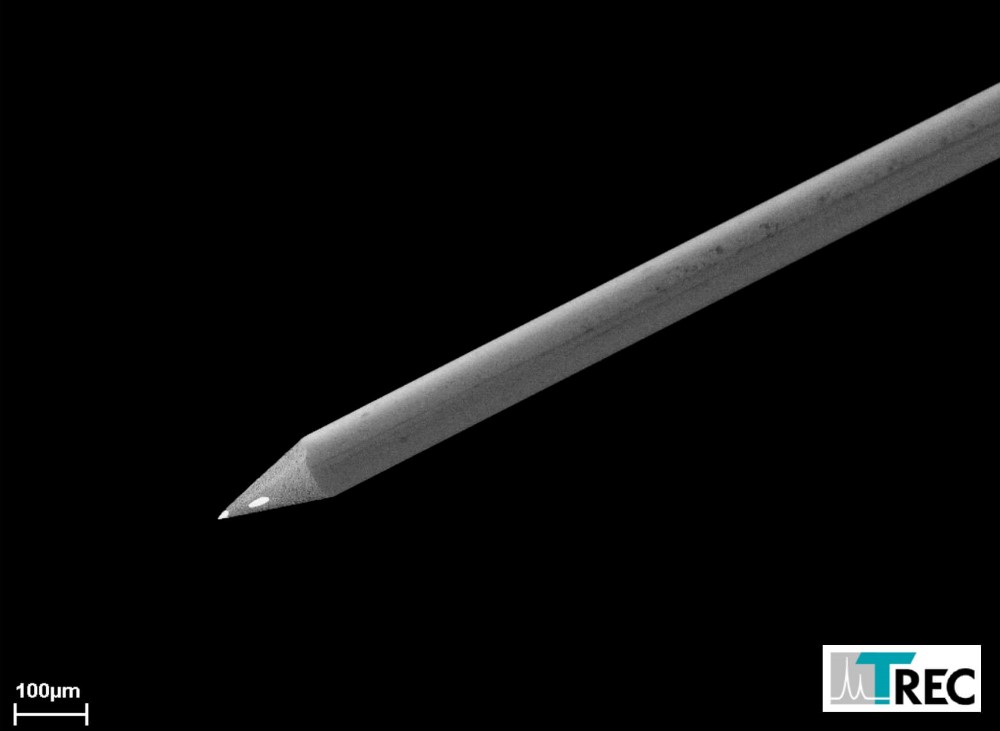 Figure 5: Scanning electron microscope (SEM) photo of a Thomas tetrode fiber with conical tip (tip shape D). This picture shows that we are able to produce tetrodes with thin shaft diameters for different applications.
2. The mechanical stability of the fibers is very high, perhaps close to the limit of what is possible at these dimensions with any material at this time. Fibers with 100µm outer diameter at an axial force of 6p (which is more than required for dura penetration) have a buckling length of 10mm. In tissue the penetration depth of these fiber electrodes can be more than 20mm. Tests in explanted pig brains showed, that the fiber microelectrodes moved straight in the brain over distances of app. 40mm without leaving the planned trajectory (see picture below).
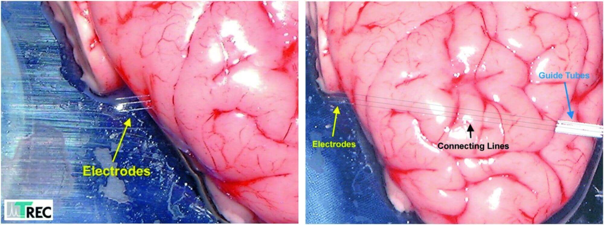
Figure 6: These pictures show a penetration test with Thomas fiber microelectrodes. The electrodes moves straight through the brain over a distance of 40.000µm although the fibers just had 80µm outer diameter. The drawn connecting lines in the rigth photo show that the exit points of the elelctrodes are exactly at the opposite side of the entrance points.
3. Due to the geometrical shape of the fibers, tissue is displaced radially during penetration, while little axial tissue compression. There is little or no re-adjustment of tissue after insertion, which might be one of the reasons why injury potentials are hardly ever seen after electrode movement has stopped.
4. The geometrical shape of the electrode tip can be made exactly and reproducibly according to the specifications, as long as it is a tip geometry that is grindable. Conical tips can be reproduced with high accuracy.
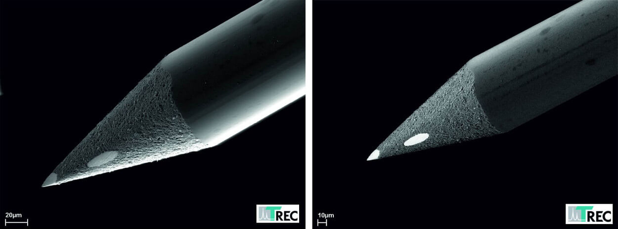 Figure 7: Thomas tetrode tip with conical tip shape. This tip is highly reproducible in contrast to twisted wire tetrode tips.
5. Additional electrolytic plating of the platinum-tungsten tips is unproblematic. We have fabricated fiber electrodes with gold-, iron-, and silver-silver/chloride plated tips. Iron plated tips can be used for electrolytic staining of recording sites. The silver-silver/chloride sites have excellent low frequency responses and DC stability.
6. Microgrooves, caused by the grinding process, increase the effective tip area at a given tip volume. This results in a tip capacitance of more than 2pF/µm2. Which is considerably higher than the tip capacitance of etched tips. The high tip capacitance seems to be responsible for the excellent signal-to-noise ratio and single unit isolation of the electrodes. (for details see [10], [11]). Fiber electrodes are well-suited for multielectrode arrays. In contrast to silicon-substrate electrodes movement control of individual electrodes is possible as reported for example by Mountcastle and others [10].
 Figure 8: Tip contact (left SEM photo) and side contact (right SEM photo) of a Thomas tetrode. One can see the microgrooves in the metal and the smooth passage between the insulating glass and the metal core conductor.
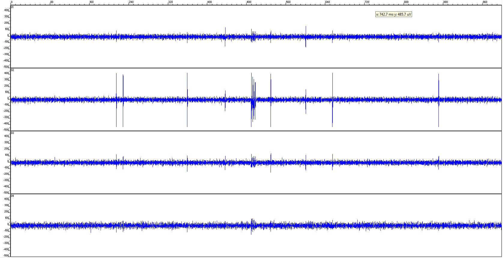 Figure 9: Example of a Thomas tetrode recording in rat cortex showing the good S/N ratio of the tetrode. Channel 2 (tip of the tetrode) has the largest spike amplitudes. The detected neuron was located close to the tetrode tip (Recording made by L. Melo-Thomas, D. Hoehl, 2014).
7. In contrast to other tetrodes presently available for neurophysiological research Thomas tetrodes can be adapted to the neural cell densities in different species and brain areas. Therefore we offer two different tip shapes (Tip A and D). Higher cell densities require smaller contact distances and also slightly higher contact tissue impedances. This is realized by pulling and grinding a tetrode fiber to yield the tetrodes with tip shape A.
Tetrode Working Priciple
The tetrode technique relies on the fact that action potential amplitude is some declining function of distance between the electrode tip and the cell. Therefore, if cellular activity is recorded from 4 closely spaced electrode contacts the relative amplitudes of the spikes on the 4 channels can be used as an additional criterion for spike separation. Moreover, if the spikes from a given cell changes shape and/or amplitude, as occurs during burst firing [12], these changes are proportionally the same on the 4 channels, thus allowing accurate identification of these cells. Not only does the method reduce errors in classification, but it also increases the number of cells that can be identified [13].
The Thomas tetrode working principle is illustrated in Figure 13. In this photomontage a tetrode tip is placed close to two neurons. Neuron A is placed closer to the recording tetrode tip as neuron B. The signals shown in Figure 13 (right side) were recorded with the tetrode based intraoperative neuronavigation system TREC SCANNER (Thomas RECORDING GmbH) in a clinical recording experiment.
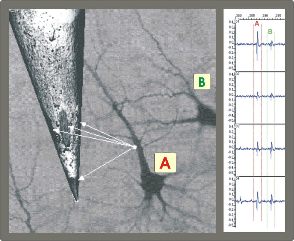 Figure 12: Left side: Illustration of the Thomas tetrode working principle. Right side: Signals recorded with a Thomas tetrode in the human brainstem.
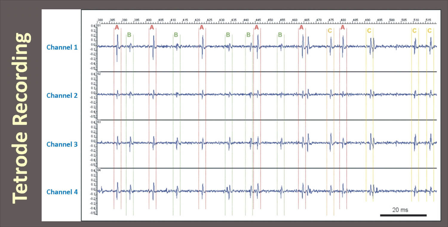 Figure 13: Extracellular recording with a Thomas tetrode in subthalamic nucleus of an anesthetized dystonia patient, University Hospital Heidelberg, D. Hoehl (TREC) in 2002. One can discern up to three different units out of the multi unit tetrode recording (unit A, B and C) based on the stereotrode effect.
Separation of spikes from different neurons is based on the assumption that spike amplitude decreases with the distance between the neuron (A in Figure 13) and the tip of the tetrode. The different lengths of the white arrows in Figure 13 demonstrate the different distances between the neuron (A) which is the signal source and the recording contacts of the tetrode. This effect causes different spike amplitudes on the four different channels of the tetrode. An example tetrode recording is shown in Figure 13 (right side). This is an amplitude pattern characteristic for neuron A. Neuron B which is located in a larger distance from the tetrode recording contacts causes generally smaller amplitudes in the recorded signal. Notice the difference in the signals of neuron A and B. Thus, the ratio of spike amplitudes measured on different contacts provides reliable information for spike discrimination. The tetrode, which is made of four very thin wires insulated from each other by quartz glass is the minimal set of electrodes that provides “triangulation” in the three-dimensional space (see [14] for details). If tetrode tips are not located in a plane, like it is the case with the Thomas tetrode, and under the idealization that neurons are point sources in a homogenous medium, the ratios of spike amplitudes will be unique for each neuron. In contrast to the tetrode, a single electrode is “spatially blind”, and its use for multi-neuron recordings can easily lead to mixing of signals from different cells whose spike amplitudes as measured at the electrode site are equal. The multi-unit nature of tetrode recordings imposes additional requirements on spike-sorting procedures. While in traditional extracellular recordings an experimentalist can position the electrode to enhance the signal from the neuron of interest, tetrodes are best positioned to record from as many cells as possible. This means that spike sorting can no longer be based on simple thresholding or on window discrimination (often implemented in hardware) – sorting of tetrode data is essentially software-based [15-17].
Finally we can conclude that the tetrode working principle is based on the following rules:
- Signal amplitude is a function of the neuron-recording site distance
- The ratios of the amplitudes of a single neuron’s action potential, as recorded on the different tetrode contacts, are much more likely to be constant from spike to spike than the amplitudes themselves
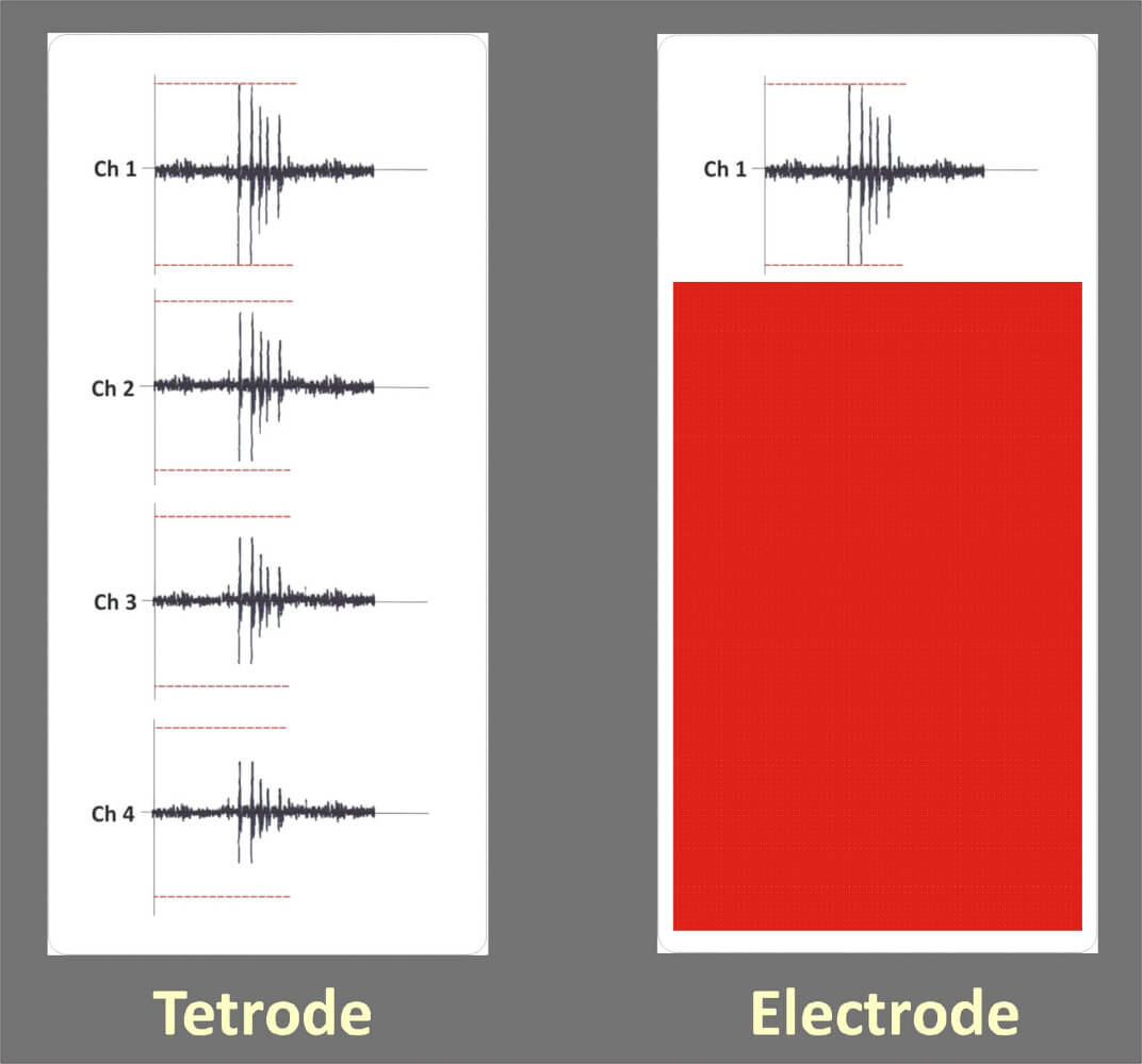
Figure 14: This picture shows a tetrode recording on the left side and just one channel of the tetrode recording representing a single electrode recording on the right side. Both elelctrodes detect a bursting neuron. The tetrode is able to identify the bursting neuron due to the fact that the amplitude changes of the action potential happen on all four channels simultaneously. The single channel of the elelctrode detects the amplitude changes of the action potential as well but the template matching spike sorter will show fail detections due to the amplitude changes. So in case of the elelctrode several single units will be detected, while the tetrode and the tetrode spike sorter will identify just a single bursting neuron.
The recording radius and spatial selectivity of an extracellular probe are important for interpreting neurophysiological recordings but are rarely measured. Moreover, an analysis of the recording biophysics of multisite probes (e.g., tetrodes) can provide for source characterization and localization of spiking single units, but this capability has remained largely unexploited. The research group of Prof. Dr. Jonathan Victor at Cornell University in New York has addressed both issues by using Thomas tetrodes quantitatively in the following publications (Mechler, F. and Victor, J. D. Dipole characterization of single neurons from their extracellular action potentials. J Comput Neurosci Published online: June 11, 2011[DOI 10.1007/s10827-011-0341-0]. 11-6-2011, and Mechler, F., Victor, J. D., Ohiorhenuan, I. E., Schmid, A., and Quin, H. Three-dimensional localization of neurons in cortical tetrode recordings. Journal of Neurophysiology 106[2], 828-848. 2011).
History of Thomas Tetrodes
The Thomas multicore microelectrodes were designed by Heribert Reitboeck and Uwe Thomas in 1987 in the Reitboeck lab at the University of Marburg, Germany (see Figure 10).
First in vivo recordings with this heptode were made by Matthias Munk. A method for classifying neuronal spikes was proposed and achieved by Kaneko et al. in 1996 by multi-unit recording using the Thomas heptodes [1]. Later Tamura described a method for quantitative analysis of heptode data recorded in the macaque inferior temporal cortex [2,3].
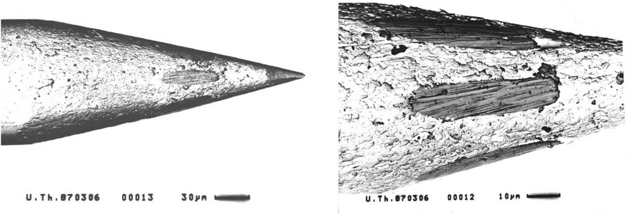 Figure 10: Scanning electron microscope photos of a Thomas heptode tip (left picture) made at March 6, 1987 by Uwe Thomas. Right side shows the metal contacts of the heptode tip isolated from each other by quartz glass. The heptode has 7 metal cores and were developed earlier than the tetrode with 4 metal cores.
The 4-cores-quartz-platinum/tungsten microelectrode (tetrode) was designed and manufactured as a result of the heptode work in summer 1993. The Thomas tetrode and heptode design was published by Schmidt in 1999 [4]. This Thomas tetrode consists of 4 metal wires each one insulated from each other by quartz glass. The metal is an alloy of 95% platinum and 5% tungsten. The tetrode fabrication method is based on the same technique as it is used for the fabrication of quartz glass insulated platinum tungsten single microelectrodes first described by Reitboeck in 1983 [5].
The result of the fabrication process is a thin fiber microelectrode with constant spaced metal wires in a concentric arrangement of three wires arranged around one center core like shown in Figure 11.
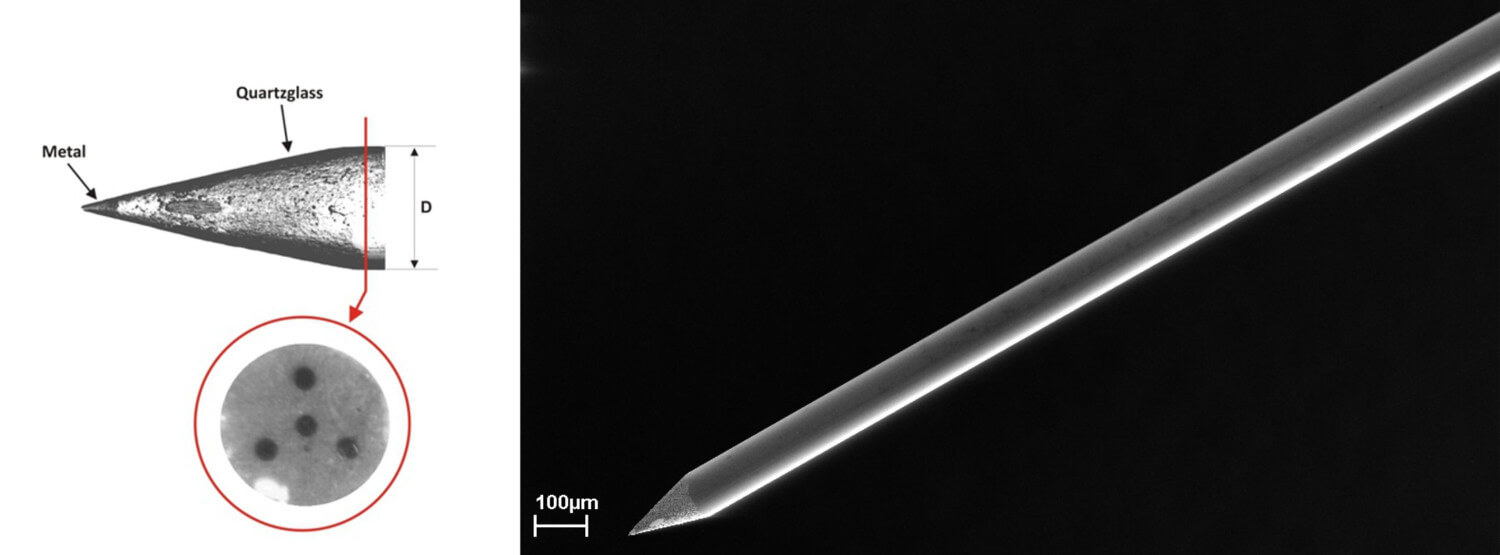 Figure 11: (left) Tetrode tip and a cross section of the tetrode fiber. One can see the 4 different tetrode metal cores (dark grey colored) insulated from each other by quartz glass (grey colored), (right) Thomas tetrode fiber with conical tip (tip shape D)
Advantages of the Thomas tetrode technique
The main differences between Thomas tetrodes and other tetrode designs presently used in neurophysiology are:
Reproducible tip geometry: based on the fact that Thomas tetrodes are made by a unique quartz glass metal fiber manufacturing process [5] the intersite spacing of the tetrode fiber is always constant for hundreds of meters of tetrode fiber raw material. This ensures a very high reproducibility of geometrical dimensions and positions of the four individual metal wires inside a TREC tetrode (see Figure 16). In contrast to this unique design other tetrodes are based for example on a twisted wire technology described for example by McNaughton [18] and Gray [13]. There the Thomas tetrodes have the advantage of a reproducible wire arrangement and intersite spacing which is required for reproducible experiment conditions (see Figure 8).

Figure 16: Cross section of a Thomas RECORDING quartz glass platinum tungsten tetrode. In the left picture one can see a light microscope photo of the cross section, the right drawing shows the dimensions of this fiber sample cross section.
Electrode impedance: The surface of a twisted wire tetrode metal contact is relatively small and usually shows impedance values of more than 1MΩ, which is too high for multi unit recordings. To lower the impedance value of this surface the metal contacts of the tetrode have to be plated with for example platinum black. This thin layer of platinum on the bare metal wire contact surface is mechanically not very stable and can be removed by shear forces, when the tetrode is introduced in brain tissue. TREC tetrodes have microgrooves in the surface of the metal contacts, caused by the special tip grinding process during the tetrode manufacture. These microgrooves increase the effective metal surface area of the tetrode contacts which causes a significant higher capacitive component of the electrode impedance (2.2pF/µm2) than the 0.5-1pF/µm2 typically measured for example on electrochemical etched microelectrode tips see ([5] for details). The tetrode contact impedance of just ground tetrode tips usually is below 1MΩ on each of the four contacts. This manufacturing technique ensures a low and reproducible impedance, well suited for multi unit recordings without the requirement of plating the metal contact surface. This technique avoids the problem of removing a thin platinum black layer on the metal wire contact surface during insertion of the tetrode tip into brain tissue by shear forces.
Neural network adaptation: Another advantage of the TREC tetrode design is that it can be adapted to different neural cell densities in different brain areas. This is explained by the following pictures in Figure 17 (A, B and C) (note that black traces are recordings and red traces are difference pairs). In Figure 17A a standard tetrode with just ground tip (site impedance of app. 500kΩ) was used for recordings in monkey cortex. The recordings on each tetrode channel are multi unit recordings. An isolation of single units from this multi unit recording by the tetrode effect was easily possible. Later the same tetrode was used for recordings in rat cerebellum. The result of this recording session was a relatively poor signal to noise ratio and a bad tetrode effect as shown in Figure 6B. It was very difficult to isolate single units from this data set. After a small modification of the tetrode tip (pulling the tip before grinding) the tetrode design was well suited for recording applications in brain areas with higher cell densities. Figure 17C shows the recording results with the modified tetrode tip in rat cerebellum. The modification of the tip causes two main changes in the tetrode design: a) the spacing between the four metal wires and b) the diameter of each wire were reduced. The smaller diameter of the metal wires causes a smaller exposed metal contact surface with a larger tip contact impedance (app. 1.2MΩ) and a smaller recording sphere for each contact. The result of the decreased intersite spacing was, that smaller signal amplitude differences of the closely spaced neurons could be better detected as before. For the first time it was possible to adapt a tetrode to the neural cell density and furthermore this adaptation was reproducible by using Thomas tetrodes. As far as we know, this kind of adaptation was not described for twisted wire tetrodes.
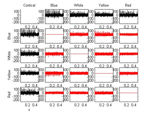 Figure 17A: Recording in monkey cortex made with a TREC tetrode. This picture shows a multi unit recording on each of the four recording channels. The tetrode tip was just ground causing a conical tip shape and impedance values of app. 500k? at f=1kHz (sinewave) on each contact.
 Figure 17B: Recording in rat cerebellum made a TREC tetrode. In this case the same tetrode was used as for the recording shown in figure A. The higher neural cell density in rat cerebellum causes pickup of more units at a time in contrast to the recordings in monkey cortex. This makes it much more difficult to isolate single units from the multi unit recording.

Figure 17C: Recording in rat cerebellum made with a modified TREC tetrode. In this case a modified tetrode was used. The tetrode tip was pulled and ground to get a double conical tip shape with a decreased intersite spacing and a small increase in contact impedance (1.2M? at f=1kHz (sinewave) on each contact. The modified tetrode tip made the tetrode more selective according to the higher neural cell density in rat cerebellum.
Reproducibility of the tip design: The high reproducible industrial manufacturing process of Thomas tetrodes makes it possible to provide tetrodes with a very high and constant quality and reproducible specifications to a large number of scientists. This ensures that recording results are comparable and reproducible according to the basic scientific rule: If results are not reproducible, don´t believe them. The tip geometry is reproducible due to a special designed tip grinding machine that allows tip grinding at always the same adjustable angle (see [5] for details).

Figure 18: Tip shape of the Thomas tetrodes is reproducible due to special designed manufacturing equipment like for example tip grinding machines with xyz manipulators for precise tip angle adjustment during the grinding process
Mechanical biocompatibility: The very smooth passage between the metal wire and the quartz glass insulation does not cause much tissue damage when the Thomas tetrode is introduced in brain tissue. Twisted wire tetrodes cause more tissue damage due to the special tip geometry of four twisted and cut wires. Silicon probes like the University of Michigan probes have sharp cutting edges and work like a knife when introduced into brain tissue. The reduction of the mechanical influence on the recording environment is important for a good recording microelectrode. A comparison between the tip geometry of a twisted wire stereotrode and a Thomas tetrode tip is presented in Figure 4. It is obvious, that the tip of the Thomas tetrode shows smooth passages between the metal contacts and the glass insulation. After using Thomas tetrodes for recordings in squirrel monkey cortex Adams et al. [9] reported concerning the tissue damage of Thomas tetrodes: “…Because tetrodes leave no visible tissue tracks and cortex becomes distorted in the flatmounting process, only data from recording sites in the immediate vicinity of a lesion could be reliably assigned to layer 4C. The tetrode enabled us often to isolate numerous cells at a single recording site…” (for details see [9]).
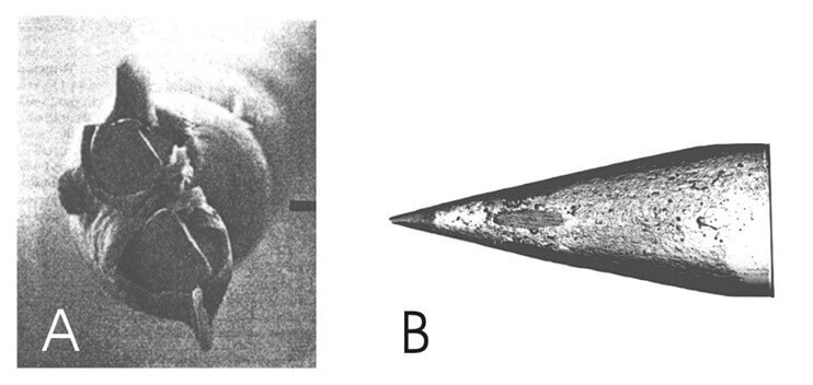
Figure 19: Comparison between a twisted wire stereotrode tip (A) and a Thomas tetrode tip (B). (A modified from [18])
Spatial resolution: TREC tetrode tips have a special arrangement of the four wires with one centre core at the very end of the tip and three contacts concentric arranged around the centre core some micrometers away from the tip contact Figure 21. With this special contact arrangement TREC tetrodes provide a better spatial resolution in comparison to twisted wire electrode contacts that are all arranged in one plane at the very end of the tetrode tip (see Figure 21). Multisite silicon probes have all contacts on one side of the shaft and therefore only one preferred recording direction.
Signal quality: One basic requirement for a reliable tetrode spike sorting is an optimal signal to noise ratio (SNR) of the recorded signal. Whilst the noise is almost identical and low across the four Thomas tetrode contacts, the spikes are clearly different like shown in Figure 20 (A, B, C and D).
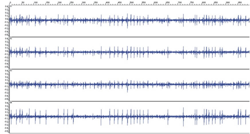 Figure 20A: Clinical tetrode recordings made in the basal ganglia of an anesthetised dystonia patient. The left pictures show some recording samples at different positions along the tetrode trajectory through the GP (Recordings made by D. Hoehl, TREC, 2001 in Heidelberg)
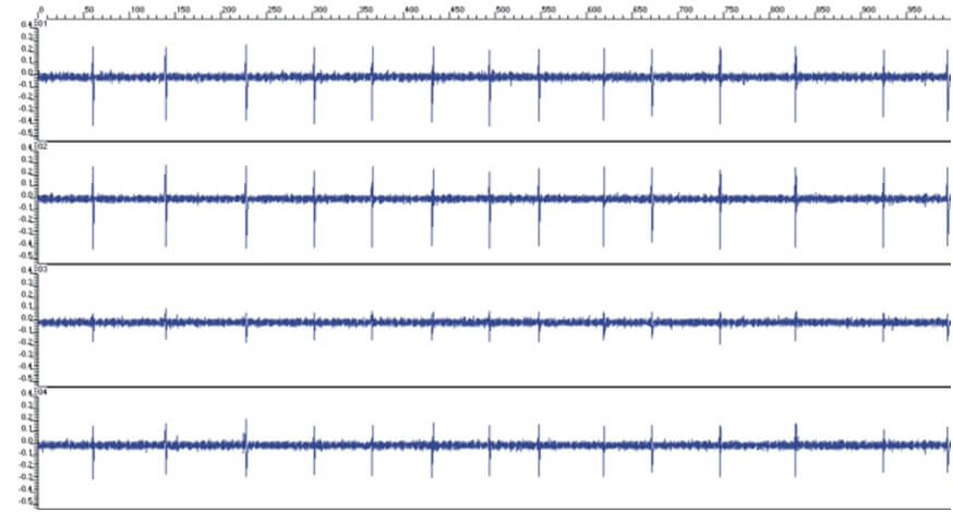 Figure 20B: The shown tetrode signals have a very good signal-to- noise ratio especially for that recording contact that is located very close to the signal source (trace #2 from top in the left picture). The other three traces show lower voltage amplitudes according to the larger distance between the recording sites and the signal source.
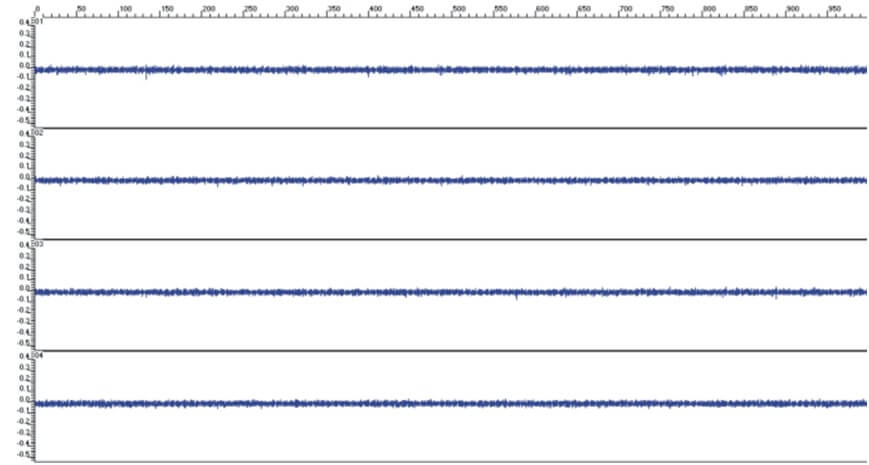 Figure 20C: This picture shows an area where no activity could be detected (quiet zone).

Figure 20D: This figure shows some recordings made with a Thomas tetrode in a human brain (Hoehl, TREC, 2002).
Deep brain recording applications: Thomas tetrodes can be placed with high precision to reach deep brain structures without stabilizing them with metal tubes. It was demonstrated by Hoehl [19] that Thomas fiber electrodes travel straight in the brain over distances up to 40mm (see Figure 6). Twisted wire tetrodes are very flexible and therefore have to be strengthened for deep brain recording applications. Hypodermic tubing has been used to strengthen wire bundle arrays for placement in deep structures. This causes much more tissue damage on the trajectory down to the recording target as with Thomas fiber tetrodes. Deep brain recordings with multisite silicon probes are also problematic because of the limited length of the forklike probes.
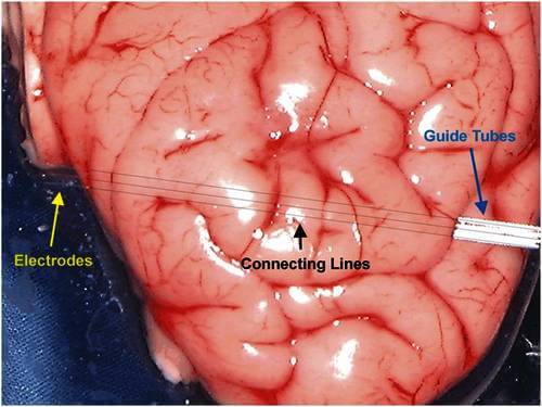 Figure 21: TREC fiber electrodes travel straight in the brain. Three electrodes were driven laterally into an explanted pig brain with a constant interelectrode spacing. All three electrodes left the brain on the opposite side in the same arrangement. The drawn connecting lines show the electrode trajectory in the brain. (Test and photo made by Dirk Hoehl, Thomas RECORDING GmbH, 2003)
Chronic recording applications: It was reported by Swadlow et al. [7], that Thomas fiber electrodes retain their excellent recording characteristics and can remain under microdrive control for periods of many months and, in one remarkable case for more than four years. The reason for this good behaviour may be, that the electrodes do not cause much tissue damage when they are introduced into the brain and therefore do not induce an excessive proliferation of neuroglia (gliosis) around the trajectory. Therefore the TREC fiber electrodes are well suited also for chronic recordings. Based on the fact, that Thomas tetrodes are made from the same raw material and manufactured with the same machines and techniques we can assume that Thomas tetrodes show a similar biocompatibility in chronic recording applications.

NEWS

PRODUCTS

SOLUTIONS

DISTRIBUTORS
 Sign Up